18J.120.070 Building Design and Placement.
The purpose of this Section is to improve the quality of new development of Commercial and other non residential uses by instituting design standards and guidelines covering new building construction and significant exterior remodels. The design guidelines and standards are intended to reduce the scale and enhance compatibility with the surrounding neighborhood.
A. Building Design Details.
1. Design Objective-Building Design Details. Buildings should be designed to incorporate features such as facades, roof forms, porches, window treatments, and architectural detailing that complements the surrounding residential architecture.
a. Building Roof Standards.
(1) Buildings shall be designed with gable, gambrel, flat, or hip roof forms. (See Figure 18J.120-9)
(2) Roof planes shall be varied by using gable ends and/or dormers.
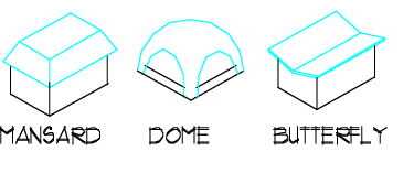
(3) The use of mansard, dome, or butterfly roof forms is prohibited. (See Figure 18J.120-10)
FIGURE 18J.120-9 – Acceptable Roof Forms
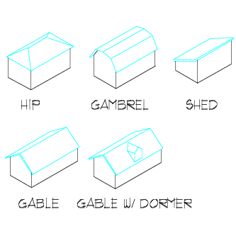
FIGURE 18J.120-10 – Unacceptable Roof Forms
b. Architectural Detailing Standards. At least one element from each of the following categories shall be included in the design of all new buildings and accessory structures: (See Figures 18J.120-11 through -12)
(1) Cornice details
(2) Trim details
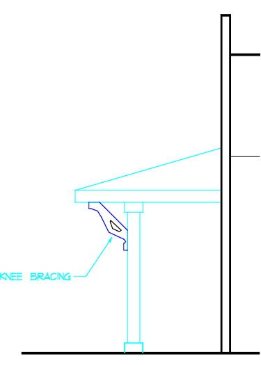
(3) Knee bracing
FIGURE 18J.120-11 – Trim Detail
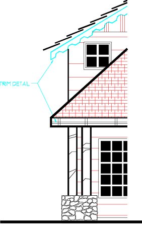
FIGURE 18J.120-12 – Knee Bracing
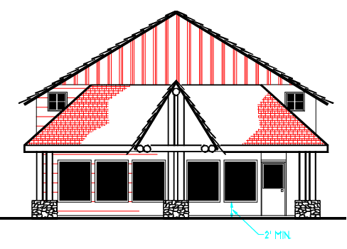
c. Window Standards. (See Figure 18J.120-13)
(1) Windows sills shall be situated at least 2 feet above the interior finished floor.
(2) The use of mirrored windows is prohibited.
(3) Window trim shall be used.
FIGURE 18J.120-13 – Window Example
d. Guidelines.
(1) Encourage architecture that is contextual or harmonious in character to residential uses through the use of color, materials, textures, and landscaping. Development should provide focal points for neighborhoods and enhance the identity of the neighborhood.
(2) Architecture should be similar to residential structures. The use of standardized "corporate or franchise" style in the design of buildings should be avoided.
B. Building Mass and Scale. Promote design in all building projects that helps to provide cohesiveness, consistency, and architectural scale and detailing without restricting architectural creativity.
1. Design Objective – Architectural Concept. Project designs shall provide a cohesive and consistent visual identity for all buildings and accessory structures in a development while responding to functional characteristics of the project.
a. Standards.
(1) All new and remodeled buildings within a multi-building complex shall achieve a unity of design through the use of similar architectural elements, such as roof form, exterior building materials, colors, and window style.
(2) Independent storage buildings, parking structures and other accessory structures shall match the principal building(s) in form, color, and use of materials and detailing.
(3) Project designs shall use the following materials: concrete, wood-looking materials (no wood sheeting), concrete masonry units (CMU), brick, metal siding or stone.
b. Guidelines.
(1) Architectural style for new construction and additions is not restricted. Rather, the evaluation of the project should be based on the quality of its design and its relationship to its surroundings and should be unique and reflect the desired character of the community.
(2) Tenant entrances in a multi-tenant building should be accentuated with similar or complementary design elements such as wall surface materials, window arrangement, color treatment, awnings, and roof forms.
(3) The use of complementary architectural elements should be considered for transitions to existing buildings on adjacent sites when such buildings conform to the standards of this Chapter.
(4) Building materials used for site features such as outdoor furniture, lighting, fences and screen walls should be consistent in architectural character with the primary on-site structures.
2. Design Objective – Architectural Elements. Architectural elements and details shall be used that tend to reduce the perceived size of a building, provide a more human scale and provide for visual and functional continuity with adjacent and neighboring commercial, office/business, civic structures which are consistent with design standards and guidelines of this Chapter.
a. Standards.
(1) Each building visible from a public roadway shall incorporate elements based on the building's gross square footage that equal or exceed the number of points found in Table 18J.120.070-1.
(2) Buildings shall be entitled to incorporate any combination of features as provided in Table 18J.120.070-2 in order to meet or exceed the required number of points. For points relating to a building wall-related design feature, the design feature need only be provided along the wall(s) that will be visible to the public roadway in order for the point to be earned.
|
Table 18J.120.070-1. Points Required for Each Building Face Based on Building Size |
|
|---|---|
|
Building Size |
Commercial, Civic, and Office/Business Use Types |
|
Less than 10,000 sq. ft. |
3 |
|
10,000 to 19,999 sq. ft. |
4 |
|
20,000 to 40,000 sq. ft. |
5 |
|
Greater than 40,000 sq. ft. |
6 |
|
Table 18J.120.070-2. Relating Design and Scale of Building Elements to the Building's Overall Form and Massing |
||
|---|---|---|
|
Element |
||
|
a. Horizontal shifts for walls >80' in length (1) |
Points |
|
|
Width of shift >20 percent of wall length |
1 |
|
|
Width of shift >30 percent of wall length |
2 |
|
|
No walls >80' |
1 |
|
FIGURE 18J.120-14 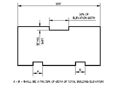
|
||
|
b. Vertical shifts of single run of ridge, cornice, or fascia >100' |
||
|
Transition in height > 4' for buildings with height of 24' or greater |
1 |
|
|
No single runs >80' |
1 |
|
FIGURE 18J.120-15 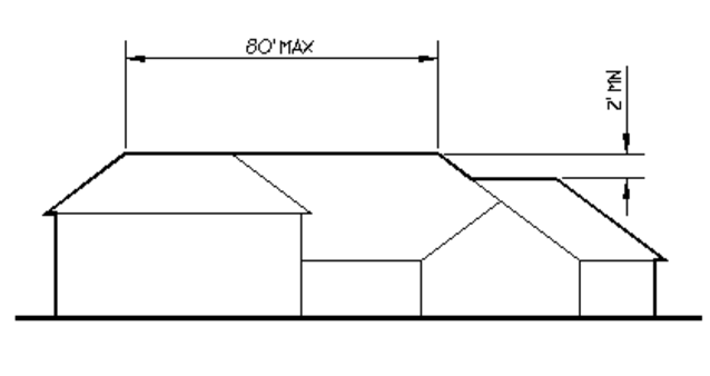
|
||
FIGURE 18J.120-16 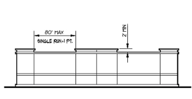
|
||
|
c. Single stand of trees within 20' of building (maximum 2 points) (2) |
||
|
Planting bed for a single stand of trees must be a minimum of 160 square feet area and 8' in width; planting used to define entrances to major buildings, exterior plazas. See Figures 18J.120-16 through -21 |
1 |
|
FIGURE 18J.120-17 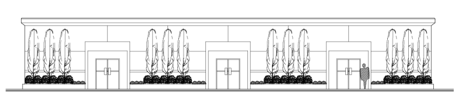
|
||
FIGURE 18J.120-18 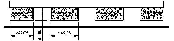
|
||
FIGURE 18J.120-19 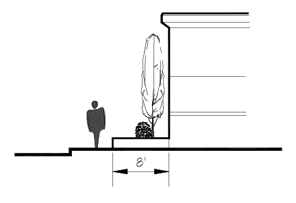
|
||
FIGURE 18J.120-20 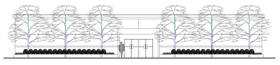
|
||
FIGURE 18J.120-21 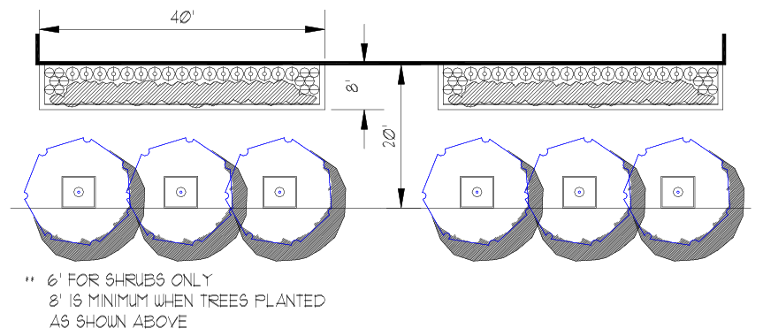
|
||
FIGURE 18J.120-22 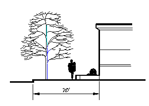
|
||
|
d. Windows |
||
|
Square footage > 30 percent of wall area visible to a public roadway |
1 |
|
|
e. Canopy or Awning (5' minimum depth) |
||
|
(Length) > 10 percent of wall length |
1 |
|
|
(Length) > 20 percent of wall length |
2 |
|
FIGURE 18J.120-23 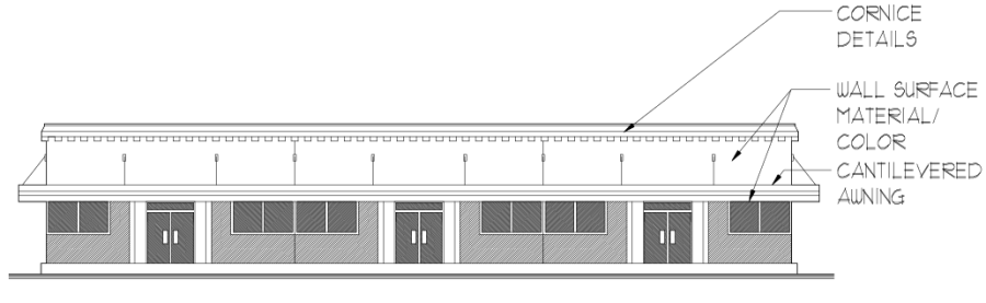
|
||
|
f. Decorative Masonry, distinguishable etchings or relief, pillars, or columns (3) |
||
|
Area covered > 10 percent of wall area |
1 |
|
|
Area covered > 30 percent of wall area |
2 |
|
FIGURE 18J.120-24 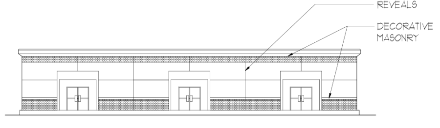
|
||
|
g. Visual wall terminus or cornice required on all building sides facing a public roadway. |
||
|
Pitched roof with fascia |
FIGURE 18J.120-25 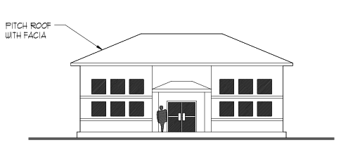
|
1 |
|
Parapet |
FIGURE 18J.120-26 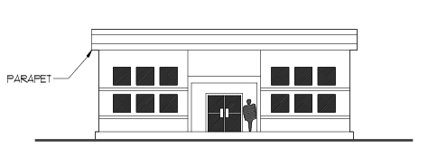
|
1 |
|
Projecting Cornice |
FIGURE 18J.120-27 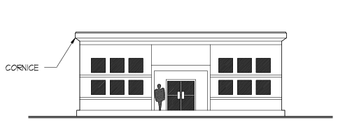
|
1 |
|
h. Vertical trellis with climbing vines or plant materials adjacent of walls |
||
|
Area covered > 15 percent of wall |
1 |
|
1The depth of the shift shall be equal to or greater than 18". Buildings having multiple offsets shall be designed to assure proportionality with adjacent wall planes on the same façade. Horizontal shifts, when required, shall be reflected by a shift or alteration in the roof design.
2The stand may include existing or planted trees and shall be in addition to required perimeter and internal parking lot landscaping. A stand of trees shall consist of a minimum of three trees, with a minimum caliper of 2" and minimum height of 8'. Trees may also be in separate tree wells within 20' of the building and bed.
3Solitary line etchings with a 8" wide band get credit, or multiple smaller reveals totaling 8" in width (i.e.. 4 x 2" bands).
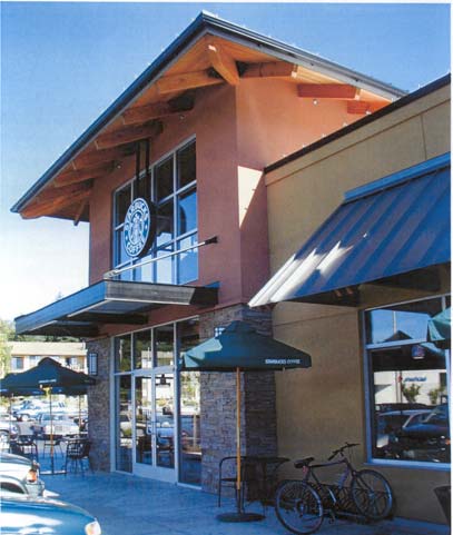
b. Guidelines. (See Figure 18J.120-28 for concept examples)
(1) Architectural details should be used that are consistent with the architectural character of the overall building and development. Within the NC zone, overall architectural style and details should complement those used in adjacent developments where these Standards have been applied to create a consistent overall character for the community. Designs should reflect the character of the community.
(2) A visual terminus should be provided on tops of buildings in the form of cornices, parapets, or other architectural features visible from the public way.
(3) Continuous awnings that conceal important architectural elements, or conflict with the character of the building, are discouraged.
(4) Awnings should maintain the visual horizontal appearance of a street front by aligning the bottom edge thereof.
(5) The use of durable, high quality materials that contribute to the overall appearance, ease of maintenance, and longevity of structures is encouraged.
(6) Windows should be included on upper stories to avoid blank upper walls.
(7) Building components such as windows, doors, eaves, and parapets should have architecturally appropriate proportions and relationship to one another.
FIGURE 18J.120-28 – Examples of Architectural Elements and Details
(Horizontal wall shifts, vertical shifts of ridge and cornice, awnings, and window treatments.)
C. Building Placement, Elevation and Street Relationship.
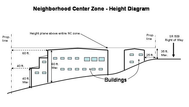
1. Design Objective – Eastside Drive (SR-509). In the Neighborhood Center, minimize the scale and visual encroachment of new development along Eastside Drive by utilizing flexible height limitations. The existing elevation of Eastside Drive is to be the determining factor for building height and design. The slope of the site will allow for a neighborhood scale structure(s) along Eastside Drive and additional height through the site as the property slopes to the west.
a. Standards.
(1) In the NC zone, no building height shall exceed 35 feet above the existing grade or elevation of Eastside Drive (SR-509). As the grade of Eastside Drive changes, the height will be measured from that portion of the road grade that is perpendicular to the new construction to ensure a gradual and subtle transition in building height commensurate to the existing road grade. (Exceptions include street lighting or power poles.) No structures shall exceed 40 feet in height at the required setback line, however, heights may be increased by one additional foot for each additional foot of setback from the property line from the portion of the building with increased height. Under no circumstance can a structure exceed 60 feet in height.
(2) The street corner shall be emphasized through:
(a) the use of a special site feature that shall include accent landscaping, accent paving, and a pedestrian feature (such as informal seating area, pedestrian bollard, or walkway lighting, etc.); and
(b) construction of a satellite building adjacent to the street frontage (comprising a minimum 2,000 square foot building) located within 25 feet of the right-of-way and no further than 100 feet from the corner of the intersection (item b is not required if the use is an industrial type use); or
(c) at least one building is located at the intersection with direct building access from the sidewalk at the intersection.
(3) Buildings provided pursuant to subsection (1)(c) above shall also be required to provide entry features pursuant to PCC 18J.120.070 E.
2. Design Objective – Single-Family (SF) Zone Building Height.
a. Standards
(1) New residential construction and remodeling in the SF zone shall meet the height limits of the zone as measured from the existing grade to the height of the highest roof surface prior to site development or modification of the structure. The existing grade shall be determined by gradeplane elevations prior to site development or modification where the new construction is proposed on the lot and building height shall be measured from the vertical distance from grade plane to the height of the highest roof surface, i.e. the top of the pitch on a pitched roof. The International Building Code definition of gradeplane applies. Any increase in height beyond what is permitted will require a Variance application as outlined in procedures contained in Title 18A-Zoning. The above supercedes other definitions for structure height in the Zoning and Building codes.
D. Entry Features.
1. Design Objective – Entry Features. In the Neighborhood Center, all buildings shall provide clearly marked building entries that allow for direct access of pedestrians from public roadways and parking areas.
a. Standards.
(1) For each developments primary buildings, at least one primary building entrance shall be oriented to a major public roadway or intersection.
(2) For each primary building entrance required by subsection (1) above, the entrance shall be clearly visible or recognizable from the right-of-way through use of at least two of the following techniques:
(a) Recessed or protruding entry,
(b) Roof line emphasis such as a decorative cornice or parapet roof.
(c) Canopy, marquee, or awning above entry.
(d) Unique decorative molding or lintel above doorway.
(e) Contrasting finish materials.
(f) Dormers;
(g) Porches; or
(h) Porticos.
|
Table 18J.120.070-3. Entry Features |
|
|---|---|
|
Element |
|
|
1. Recessed or protruding entryway |
FIGURE 18J.120-30 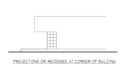
|
|
2. Roofline emphasis |
FIGURE 18J.120-31 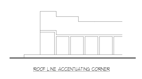
|
|
3. Special window treatment, awning, or canopy |
FIGURE 18J.120-32 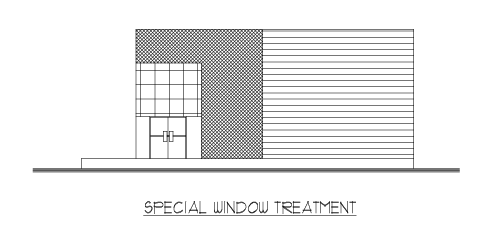
|
|
4. Locate building no further than the landscape setback from property lines |
|
b. Guidelines.
(1) Building entries should be enhanced with a combination of landscaping, weather protection, pedestrian amenities and architectural features. Within the NC zone, landscaping, pedestrian amenities and architectural features shall complement those used within the required landscape buffer.
(2) The use of covered walkways is encouraged between structures.